Pipe Friction Loss Calculator: Free 2026 Tool + Fire Hose
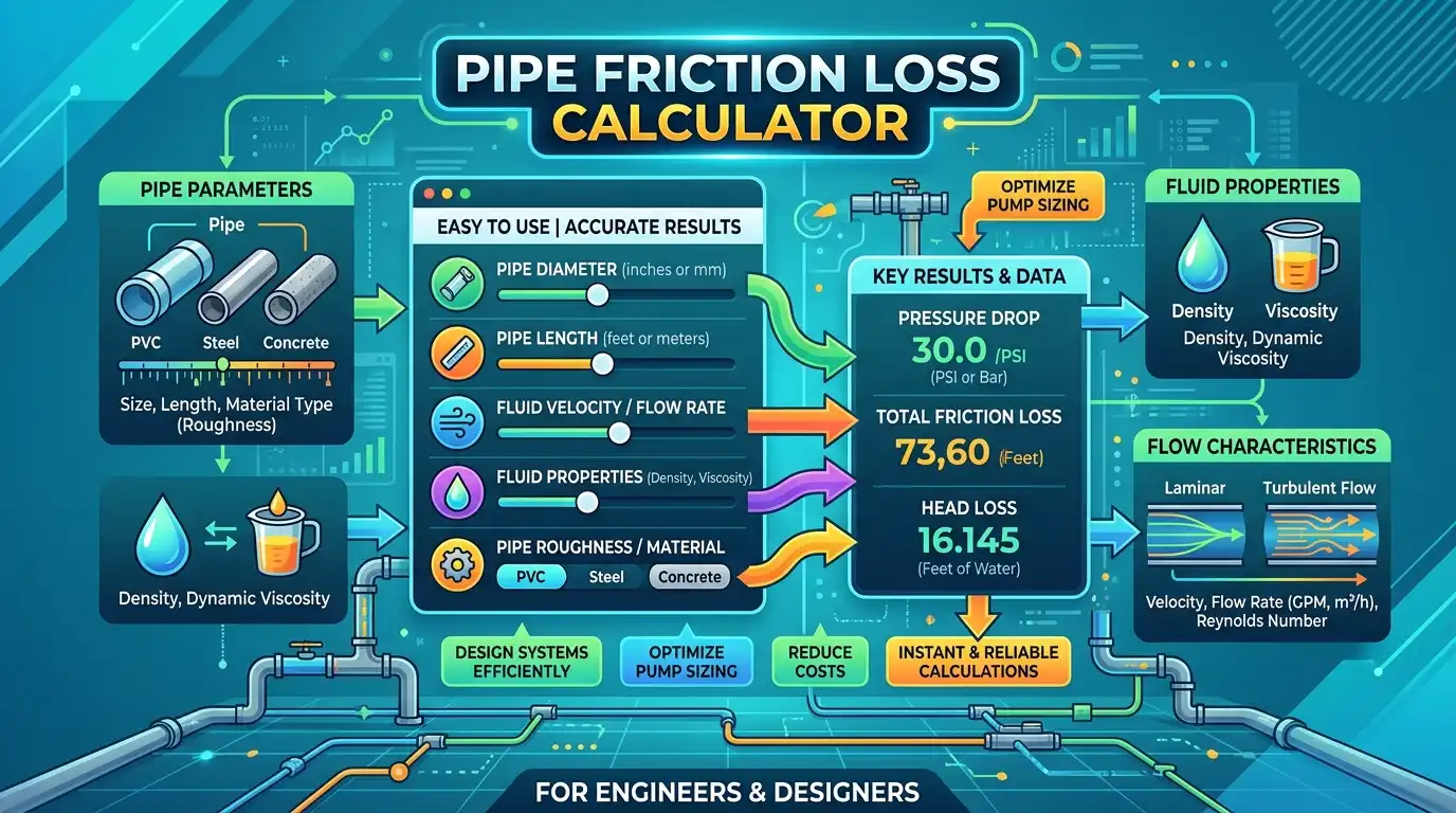
Table of Contents
TogglePipe Friction Loss Calculator: Water Pipe & Fire Hose
This pipe friction loss calculator helps estimate pressure loss when water moves through a pressurized pipe or fire hose. It is useful for plumbing, irrigation, water distribution, pump sizing, hydraulic checks, and fireground hose calculations.
The tool calculates straight-pipe friction, velocity, head loss, pressure loss, fitting losses, elevation effects, and pump pressure for fire-hose scenarios. Accurate inputs matter because friction rises rapidly as flow increases and falls sharply as the inside diameter becomes larger.
For fire protection work, hose construction and the actual tested friction-loss coefficient can change the result. NFPA technical material explains the relationship between hose friction, diameter, flow, and pressure loss, so department testing and current procedures should take priority over generic coefficients.
How Pipe Friction Loss Calculator Works
The water-pipe mode uses the Hazen-Williams equation for pressurized water flow. It estimates major friction loss from flow rate, pipe length, inside diameter and the Hazen-Williams C-factor.
Minor losses are then estimated with loss coefficients, commonly written as K-values. These account for elbows, tees, valves, entrances and exits rather than pretending that every hydraulic system is only a straight piece of pipe.
The fire-hose mode uses the standard fire-service relationship FL = C × Q² × L. In that equation, Q is flow in hundreds of GPM and L is hose length in hundreds of feet.
For the Hazen-Williams calculation, hf is head loss in feet of water, L is pipe length in feet, Q is flow in GPM, C is the roughness coefficient, and d is actual inside diameter in inches.
Pressure loss from water head is approximately 0.433 PSI for every foot of water head. Elevation is also converted using approximately 0.433 PSI per foot of vertical rise.
The fire-hose equation follows the fire-service convention of using a hose-specific C coefficient. NFPA technical material also derives the fire-service relationship from Darcy-Weisbach and explains why hose construction and internal diameter influence friction loss.
See NFPA technical material on fire-hose friction loss for the engineering basis and limitations of the simplified fire-service equation.
Step-by-Step Example Calculation
Suppose a water system sends 400 GPM through 500 feet of 4-inch inside-diameter pipe. Assume a Hazen-Williams C-factor of 150, six 90-degree elbows, one tee, one valve, an entrance K of 0.5, an exit K of 1.0, and a 10-foot elevation gain.
The straight-pipe Hazen-Williams calculation gives about 16.2 feet of head loss. Converting that value to pressure gives approximately 7.0 PSI of straight-pipe friction loss.
At 400 GPM through a 4-inch bore, the average velocity is about 10.2 feet per second. The combined K-value for the example fittings is 4.4, producing approximately 3.1 PSI of minor-loss pressure.
The 10-foot elevation gain adds about 4.3 PSI. The resulting pressure change is therefore about 14.4 PSI before any additional equipment, pump inefficiency or unlisted components are considered.
What Affects Your Pipe Friction Loss Result?
Pipe friction is controlled by several hydraulic variables, but flow rate and inside diameter are especially important. A small change in bore can create a large change in pressure loss because diameter appears as a high power in the Hazen-Williams equation.
Flow Rate and Velocity
Increasing flow increases friction rapidly. In the Hazen-Williams equation, flow is raised to approximately the 1.85 power. In the fire-hose equation, flow is squared, so doubling GPM produces roughly four times the hose friction when everything else stays constant.
Velocity is another useful diagnostic. Very high velocity can indicate that a pipe is undersized for the intended duty, even when the calculated friction loss initially appears manageable.
Pipe Diameter and Actual Bore
Always use the actual inside diameter when possible. Nominal pipe size is a labeling convention and does not necessarily equal the waterway diameter. Wall thickness, schedule, lining and construction can change the available flow area.
This is particularly important for older systems and fire hose. NFPA material notes that fire-hose friction varies with construction, lining roughness and internal diameter, so a nominal size alone cannot guarantee a specific pressure loss.
Friction Loss Calculator Fire Hose Inputs
A friction loss calculator fire hose calculation is different from a municipal water-pipe calculation. Fireground hose calculations normally use the C × Q² × L relationship rather than simply applying a generic Hazen-Williams coefficient.
The coefficient should reflect the hose type and the value used by the department, manufacturer or applicable training reference. Common training values include C = 15.5 for 1¾-inch hose, C = 2 for 2½-inch hose, C = 0.8 for 3-inch hose, and C = 0.2 for 4-inch supply hose.
Fire Hose Friction Loss Calculator and Hose Condition
Hose age, lining condition, construction and internal diameter can affect real-world friction. A generic coefficient is therefore a planning value rather than a substitute for tested hose performance.
If your department has a tested friction-loss chart or current standard operating guideline, use that information when it differs from the calculator’s default coefficient.
Fittings, Valves and Other Minor Losses
Long straight pipe is only one source of hydraulic loss. Elbows, tees, valves, entrances, exits and contractions can add measurable resistance, particularly in compact systems with many fittings.
The calculator separates these minor losses so you can see whether the main pressure penalty comes from straight pipe or from the fittings connected to it.
Elevation and Pump Pressure
Water moving uphill requires additional pressure even if the pipe itself is perfectly smooth. A useful planning conversion is about 0.433 PSI for each foot of vertical rise.
Fireground pump calculations commonly combine nozzle pressure, hose friction, appliance losses and elevation. The calculator therefore keeps these values separate instead of hiding them inside one unexplained number.
Typical Friction-Loss Ranges by Scenario
The table below provides practical reference points rather than guaranteed design values. Actual results change with pipe bore, hose construction, C-factor, flow and the number of fittings.
| Scenario | Typical Flow | Typical Length | Reference Coefficient | Approx. Friction Loss |
|---|---|---|---|---|
| 1¾″ fire attack hose | 150 GPM | 200 ft | C = 15.5 | 69.8 PSI |
| 2½″ fire hose | 200 GPM | 200 ft | C = 2 | 16 PSI |
| 3″ supply hose | 300 GPM | 200 ft | C = 0.8 | 14.4 PSI |
| 4″ supply hose | 500 GPM | 200 ft | C = 0.2 | 10 PSI |
| 4″ smooth water pipe | 400 GPM | 500 ft | C = 150 | ≈7.0 PSI |
Fire-hose values in particular should be treated as reference calculations. A department’s tested coefficient can differ from generic training values, and fittings or appliances can add pressure loss beyond straight hose friction.
Common Pipe Friction Loss Calculation Mistakes
One common mistake is entering nominal pipe size instead of actual inside diameter. Another is forgetting that a longer pipe creates proportionally more major friction loss.
Users also sometimes calculate fire-hose friction with the wrong flow units. In the standard C × Q² × L relationship, GPM is divided by 100 and hose length is divided by 100 before multiplication.
Finally, avoid treating the straight-pipe result as the complete hydraulic requirement. Fittings, valves, elevation, appliances and nozzle pressure can materially change the pressure that a pump must provide.
Frequently Asked Questions
What is pipe friction loss?
Pipe friction loss is the reduction in pressure or hydraulic head caused by resistance as fluid flows along a pipe or hose. It depends on flow rate, inside diameter, length, surface characteristics and fluid properties. Fittings, valves and elevation can create additional losses that should be calculated separately.
How do you calculate friction loss in a pipe?
For pressurized water, the Hazen-Williams equation is commonly used to estimate major friction loss from flow, length, inside diameter and the C-factor. Darcy-Weisbach is another general method that uses velocity, Reynolds number and pipe roughness. Minor losses can then be added using K-values.
What is the fire hose friction loss formula?
The standard fire-service relationship is FL = C × Q² × L. Flow Q is expressed in hundreds of GPM and hose length L in hundreds of feet. The coefficient C depends on hose size and construction. Always compare generic coefficients with current department procedures and tested hose data.
What is the friction loss for 1¾-inch fire hose?
A commonly used training coefficient for 1¾-inch hose is C = 15.5. At 150 GPM through 200 feet, the calculation is 15.5 × 1.5² × 2, producing about 69.8 PSI of hose friction loss. Actual hose performance can differ, so verified department data should take precedence.
What is the friction loss for 2½-inch fire hose?
A commonly used fire-service coefficient for 2½-inch hose is C = 2. At 200 GPM through 200 feet, FL = 2 × 2² × 2, giving 16 PSI. The result represents hose friction only and does not automatically include nozzle pressure, elevation or appliance losses.
Does pipe diameter affect friction loss?
Yes. Diameter has a major effect on friction loss. For the Hazen-Williams equation, inside diameter is raised to approximately the 4.87 power in the denominator. That means a relatively small increase in actual bore can substantially reduce pressure loss when flow and pipe length remain unchanged.
Does doubling flow double friction loss?
No. Friction loss normally rises faster than flow. Hazen-Williams uses approximately Q^1.85, while the standard fire-hose formula uses Q². Therefore, doubling flow can produce roughly 3.6 times the Hazen-Williams friction component or four times the fire-hose friction component when other variables stay constant.
Should I use Hazen-Williams or Darcy-Weisbach?
Hazen-Williams is convenient for pressurized water systems and commonly used water-distribution calculations. Darcy-Weisbach is more general because it incorporates fluid properties and a friction factor based on Reynolds number and roughness. For non-water fluids, unusual temperatures or engineering design work, Darcy-Weisbach may be more appropriate.
Related Calculators
These CalculatorSuiteHub tools cover nearby water, drainage and property-system calculations that can complement a hydraulic planning workflow.

Asrar Ahmad
Founder of CalculatorSuiteHub.com and Rankify SEO & AI Agency. Specializes in SEO, technical content writing, WordPress development, and AI-powered digital solutions. Builds accurate calculators and helps businesses grow online.