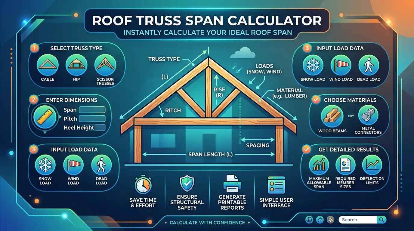
Planning a house, garage, workshop, barn, addition, or other framed building requires accurate roof geometry before ordering trusses. This roof truss span calculator converts your span, pitch, building length, overhang, spacing, and planning loads into useful preliminary numbers.
You can estimate the number of trusses, peak rise, top-chord length, roof-plane area, tributary load, and simplified load per truss. The tool is designed for planning and quantity checks, not for replacing an engineered truss design.
Written for CalculatorSuiteHub.com by Asrar Ahmad
Roof Truss Span Calculator
Enter your building geometry and representative roof loads below. The default example uses a 30-ft span, 40-ft building length, 6/12 pitch, and 24-in. truss spacing.
Planning estimate:
This calculator uses roof geometry and user-entered area loads for preliminary planning. It does not size truss members, webs, connector plates, bearings, bracing, uplift connections, or foundations. Verify the final truss design with the truss manufacturer, structural professional, and applicable local requirements before construction.
How This Calculator Works
A roof truss is an engineered structural assembly rather than a single beam. The outer geometry can be calculated with basic trigonometry, while member sizes, joints, webs, connectors, bracing, and load combinations require project-specific engineering.
This tool therefore separates geometric calculations from structural capacity. It gives you useful planning values without presenting a generic span number as an engineered approval.
Formula & Explanation
Half-Span = Span ÷ 2
Rise = Half-Span × (Pitch ÷ 12)
Slope Factor = √(1 + (Pitch ÷ 12)²)
Top Chord = (Half-Span + Overhang) × Slope Factor
Truss Count = ceil(Building Length ÷ Spacing) + 1
Tributary Width = Truss Spacing
Line Load = Total Area Load × Tributary Width
Simplified Load Per Truss = Total Area Load × Tributary Width × Span
Span is the horizontal distance the truss must clear between its bearing locations. Pitch expresses vertical rise for every 12 inches of horizontal run.
Spacing determines the tributary width assigned to each truss. At 24 inches on center, each interior truss represents a 2-foot-wide strip of the roof plan.
The simplified load-per-truss calculation assumes the entered area load applies uniformly over the horizontal tributary area. Actual design loads can include different load cases and combinations.
The Truss Plate Institute states that ANSI/TPI 1 establishes minimum requirements for the design and construction of metal-plate-connected wood trusses, including design procedures for truss members and joints.
Consider a 30-foot-wide garage that is 40 feet long. Assume a symmetrical 6/12 gable roof, 1-foot horizontal overhang at each eave, and trusses at 24 inches on center.
First, divide the 30-foot span by two. The horizontal run is 15 feet. A 6/12 pitch means the roof rises 6 inches for every 12 inches of horizontal run.
The peak rise is therefore 15 × 6/12 = 7.5 feet above the bearing line. This gives the basic roof height before adding any separate heel height.
The slope factor is √(1 + 0.5²), or about 1.118. Including the 1-foot horizontal overhang gives a horizontal top-chord projection of 16 feet.
The approximate top-chord length is 16 × 1.118 = 17.89 feet per side. The actual manufactured chord can differ because of heel details, joints, cuts, and the specific truss design.
For truss quantity, convert 24 inches to 2 feet. Then calculate ceil(40 ÷ 2) + 1 = 21 truss positions. This is the same basic count convention used for a regular straight run with a truss at each end.
If the total planning area load is 50 psf, the simplified load per interior truss is 50 × 2 × 30 = 3,000 pounds. This is a tributary-load estimate, not a member-capacity calculation.
What Affects Your Roof Truss Span Result?
Building Span and Bearing Locations
The clear span is the most important geometric measurement because it defines the horizontal distance between the truss bearings. Do not confuse building width with the sloped length of the roof surface.
A 30-foot building width does not mean a 30-foot sloped top chord. Pitch and overhang determine the sloped chord length after the horizontal span has been established.
Roof Pitch and Peak Rise
Pitch changes the vertical rise and the length of each top chord. For the same 30-foot span, a 4/12 roof has a lower ridge than a 8/12 roof.
Pitch can also affect the truss configuration, attic clearance, roofing area, and wind behavior. Specialized trusses such as scissor or attic designs require additional geometry beyond this basic symmetrical gable model.
Truss Spacing
Truss spacing determines how much roof plan area is assigned to each truss. Common residential layouts often use 24 inches on center, while 16-inch and 19.2-inch layouts are also used.
Closer spacing generally reduces tributary width per truss but increases the number of trusses. The selected spacing should come from the engineered design rather than being changed simply to make the quantity fit a preferred number.
Deck Beam Span Calculator vs. Roof Truss Design
A deck beam span calculator addresses a beam supporting joists and is normally governed by beam bending, shear, deflection, section properties, and support conditions. A roof truss distributes forces through multiple interconnected members.
Because the structural systems are different, a deck beam span result should not be substituted for a roof truss span decision. The same span can require very different structural solutions depending on the load path.
Steel Beam Span Calculator
A steel beam span calculator is designed around a steel section and its structural properties. Inputs can include steel grade, section size, load, support condition, bending, shear, and deflection limits.
A steel roof truss is different because it uses a triangulated arrangement of members and connections. If a project uses a steel truss, the actual section properties, connection details, bracing, and load combinations must be evaluated as a complete system.
Metal Beam Span Calculator
Metal beam calculations can cover structural steel, cold-formed steel, or other manufactured sections. Their allowable span depends on the actual member profile and design assumptions.
Do not interpret a metal beam span as a generic roof-truss capacity. A beam and a truss have different load paths, and a truss may require several members to work together to transfer forces to its bearings.
Steel Beam Span Table Calculator
A steel beam span table calculator can be useful when comparing beam options, but published tables are tied to specific assumptions. Changing load, section, grade, support condition, or deflection criteria can change the permitted result.
Roof trusses work similarly in one important respect: a published span range is not a universal approval. The final design must match the actual span, pitch, spacing, loading, material, connections, bracing, and support conditions.
Roof Dead Load
Dead load includes permanent components such as roof covering, sheathing, insulation, ceiling finishes, framing, and permanently attached equipment. Heavy tile, additional layers, solar equipment, or mechanical equipment can materially change the required design.
The calculator separates covering, sheathing, ceiling and framing allowances so that you can see which assumptions make up the planning load instead of hiding everything inside one generic number.
Snow and Roof Live Loads
Snow loads vary significantly by location and project conditions. A snow value entered into this tool is a planning input and should not be confused with a complete code-based roof snow calculation.
Roof live or maintenance loads can also apply when required. The governing project design may use separate top-chord, bottom-chord, snow, wind, concentrated-load, and other load cases.
Wind, Uplift and Bracing
Wind is especially important because roof trusses can experience uplift as well as gravity loading. Simply adding a wind pressure number to a vertical gravity load does not reproduce the required wind load combinations.
Temporary and permanent bracing are also part of the structural system. Never cut, drill, remove webs, or otherwise modify a manufactured truss without approval from the responsible designer.
Roof Truss Span Reference Table
There is no single universal maximum span for every roof truss. Truss type, material, pitch, spacing, loads, bearing, bracing, connector design, and project conditions all affect the engineered result.
Truss Type
Common Planning Use
Geometry
Important Design Consideration
King Post
Short-span roofs, sheds and small additions
Simple pitched triangle
Limited interior web configuration
Fink / W
Common residential roofs
W-shaped internal webs
Span and load capacity depend on the engineered design
Howe
Residential and longer-span applications
Vertical and diagonal web system
Member and connection design must be verified
Scissor
Vaulted or cathedral ceilings
Sloping bottom chord
Requires separate bottom-chord geometry
Attic
Roof space intended for usable room area
Raised bottom-chord configuration
Interior clearance changes the truss design
Mono
Sheds, lean-tos and single-slope structures
Single roof slope
Not represented by the symmetrical gable formula
Use this table to understand truss families rather than to select a structural capacity. The final truss should be ordered from an engineered layout that reflects the actual project conditions.
Roof Truss Span Planning Checklist
Measure the span: identify the actual bearing-to-bearing width.
Measure the building length: this determines how many trusses repeat along the ridge.
Confirm pitch: record the rise for every 12 inches of horizontal run.
Confirm spacing: use the spacing specified by the truss designer.
Identify roof materials: include the actual covering and sheathing assembly.
Check permanent loads: include ceilings, insulation, solar equipment, mechanical equipment, and other fixed loads where applicable.
Check snow and wind: use the governing local design information and required load combinations.
Review bracing: follow the manufacturer’s temporary and permanent bracing requirements.
Order from the engineered design: do not use a generic online span as a construction approval.
Frequently Asked Questions
How do I calculate roof truss span?
Measure the horizontal distance between the truss bearing locations. For a symmetrical gable roof, divide the span by two to obtain the run. Then use the pitch to calculate rise and the Pythagorean theorem to calculate the basic top-chord length.
How many roof trusses do I need for a 40-foot building?
At 24 inches on center, a regular 40-foot truss run gives ceil(40 ÷ 2) + 1 = 21 truss positions. This is a basic quantity calculation. Hip systems, girder trusses, openings, special end conditions, and engineered layouts can require additional or different truss pieces.
What is a typical roof truss spacing?
Twenty-four inches on center is common in residential construction, while 16 and 19.2 inches are also used. The correct spacing depends on the truss design, roof covering, sheathing, loads, span, and project requirements. Always use the spacing shown on the engineered truss drawings.
How far can a Fink roof truss span?
A Fink or W truss does not have one universal maximum span. Different lumber grades, chord sizes, pitch, spacing, loads, web layouts, and connection designs produce different capacities. A published span range can be useful for planning, but the project-specific engineered truss controls the allowable span.
Does roof pitch affect truss span?
Pitch changes the rise and top-chord geometry for a given horizontal span. It can also influence the internal truss arrangement and load behavior. Two trusses with the same horizontal span but different pitches can therefore require different engineering even though their basic width is identical.
Can I use a steel beam span calculator for a roof truss?
No. A steel beam span calculator normally evaluates a beam section for bending, shear and deflection. A roof truss uses multiple interconnected members and joints. A steel beam may be part of a roof structure, but its result should not be treated as the capacity of a wood or steel roof truss.
Does this calculator replace a structural engineer?
No. The calculator provides geometry, quantity, and simplified tributary-load information for preliminary planning. It does not design chord sizes, web members, connector plates, bracing, uplift connections, bearings, or foundations. Construction should follow the applicable engineered truss drawings and local requirements.
What loads should I enter for a roof truss?
Enter the permanent roof loads and applicable variable loads that belong to your project. Covering, sheathing, ceiling materials, insulation, equipment, snow, maintenance loads, and other permanent or temporary forces can matter. Wind should be evaluated using the required code load cases rather than simply added as gravity pressure.
Related Calculators
These CalculatorSuiteHub tools are relevant to construction planning and home improvement work.
Accurate truss planning begins with the correct span, building length, pitch, overhang, spacing, and project loads. These inputs establish the basic geometry and tributary loading needed for the next stage of design.
Use the calculator to check measurements, estimate truss quantities, understand roof geometry, and prepare information for your truss supplier. Before construction, compare the result with the engineered drawings and applicable local requirements.
Asrar Ahmad
Founder of CalculatorSuiteHub.com and Rankify SEO & AI Agency. Specializes in SEO, technical content writing, WordPress development, and AI-powered digital solutions. Builds accurate calculators and helps businesses grow online.
“`html Fire Protection & Water Supply Hydrant Flow Test Calculator: Fast Fire Flow Estimate A hydrant flow test calculator helps fire protection professionals, water-system planners, inspectors, engineers, and facility managers estimate water flow from field pressure readings. Enter static pressure, residual pressure, pitot pressure, outlet diameter, and discharge coefficient to calculate flow in gallons per…
Updated September 2026 · U.S. Cost Estimates Pressure Washing Estimate Calculator: Get Your 2026 Cost Estimate Use this pressure washing estimate calculator to estimate professional pressure washing costs based on surface type, square footage, condition, and common pricing factors. It is designed for U.S. homeowners and property owners who want a realistic starting point before…
Pipe Friction Loss Calculator: Water Pipe & Fire Hose By Asrar Ahmad · CalculatorSuiteHub.com This pipe friction loss calculator helps estimate pressure loss when water moves through a pressurized pipe or fire hose. It is useful for plumbing, irrigation, water distribution, pump sizing, hydraulic checks, and fireground hose calculations. The tool calculates straight-pipe friction, velocity,…
Home Improvement & Construction Cost Residential Construction Cost Per Square Foot by ZIP Code Calculator Planning a new home build starts with a realistic construction budget. This residential construction cost per square foot by zip code calculator helps homeowners, builders and property investors estimate construction costs. It uses ZIP code, finished square footage, quality level…
Spray Foam Insulation Cost Calculator Estimate your spray foam project using area, foam type, thickness, application, existing insulation, access, regional labor conditions, and realistic installation allowances. The calculator converts surface area and foam depth into board feet, then builds a low, typical, and high planning estimate. Calculate Your Spray Foam Insulation Cost Enter your project…
Home Improvement & Construction Cost Gutter Installation Cost Calculator: 2026 Estimate A gutter installation cost calculator helps homeowners estimate a realistic project budget. This tool uses linear gutter footage rather than house square footage. It also considers material, system style, building height, roofline complexity, downspouts, gutter guards, old-gutter removal, fascia work and a measurement allowance….